
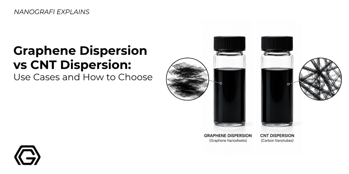
Graphene Dispersion vs CNT Dispersion: Use Cases and How to Choose
If you have ever tried to formulate a conductive ink, a battery slurry, or an anti-static coating, you already know the real bottleneck is rarely the raw nanomaterial itself. It is getting that nanomaterial to stay evenly suspended, without clumping, settling, or losing conductivity, long enough to actually process it. That is the entire discipline behind a nanomaterial dispersion, and it is exactly where graphene and carbon nanotubes (CNTs) start to behave very differently.
Both materials are built from the same sp2-hybridized carbon lattice, yet their geometry, a flat two-dimensional sheet for graphene versus a rolled, one-dimensional tube for CNTs, changes almost everything downstream: how they exfoliate Or debundle, which solvents wet them, how much loading you need for conductivity, and which industry ends up using them. This article walks through the practical differences and, more importantly, where each dispersion type genuinely outperforms the other.
What a Dispersion Actually Is (and Why It's Not a Solution)
A true solution forms when a solute dissolves at the molecular level. A dispersion is different: solid nanoparticles or nanosheets are suspended in a liquid medium, held apart from each other by surfactants, functional groups, or steric stabilizers so they do not re-aggregate. Buyers frequently blur this line when comparing specs, even though the differences between solutions and dispersions directly affect shelf life, required mixing energy, and how a product should be stored before use.
For both graphene and CNTs, the underlying problem is the same: neither material has a thermodynamically favorable solvent in which it spontaneously separates into individual sheets or tubes. Researchers studying design rules for graphene and CNT solvents have shown that the different geometry of the two materials changes how effectively a given solvent or dispersant molecule can wet, debundle/exfoliate, and sterically or electrostatically stabilize them
meaning a formulation that stabilizes graphene will not necessarily work for CNTs, and vice versa.
Graphene Dispersions: Flat Sheets, Restacking Problems
Graphene dispersions are produced mainly through liquid-phase exfoliation of graphite or through processing of graphene oxide, followed by stabilization in water, alcohols, or NMP-type solvents. The core challenge is restacking: because graphene sheets are flat and have a huge surface area, strong pi-pi stacking interactions pull them back together once the exfoliation energy is removed. Getting a stable, single-to-few-layer dispersion typically means pairing the right solvent or utilizing a surfactant/covalent functionalization step in aqueous/polar media. Even well-prepared graphene oxide dispersions can agglomerate or flocculate if pH or ionic strength shifts during storage, and that same sensitivity to flake thickness and lateral size runs through most reported graphene nanoplatelet properties.
Once stabilized, pristine graphene or reduced graphene oxide dispersions tend to form continuous, thin conductive films at relatively low thickness, which is exactly why they have become attractive for printed electronics materials and flexible circuit substrates.
CNT Dispersions: High Aspect Ratio, Bundling Problems
Carbon nanotubes come out of synthesis as tangled bundles held together by van der Waals forces. Whether you are working with single-walled (SWCNT) or multi-walled (MWCNT) material changes the dispersion behavior significantly, and the trade-offs between SWCNT and MWCNT grades usually end up driving most of that formulation decision on their own.
The upside of CNTs is their extremely high aspect ratio (length to diameter), which lets a small mass fraction bridge large distances inside a matrix and build a continuous conductive network, one of the core carbon nanotube fundamentals, properties and industrial applications that keeps driving new formulation work. The downside is exactly that same geometry: without post-treatment (oxidation, surfactant selection, or functionalization) CNTs re-aggregate quickly in suspension, which is one reason surfactants like Triton X-100 are so widely used to keep CNT networks homogeneous during processing, as documented in recent buckypaper research. When CNTs are vacuum-filtered into a free-standing conductive sheet rather than kept in liquid form, the result is a buckypaper, a self-supporting mat that inherits both the strength and the conductivity of the tubes packed inside it.
Graphene vs CNT Dispersion: Quick Comparison
|
Property |
Graphene Dispersion |
CNT Dispersion |
|
Geometry |
2D sheet |
1D tube |
|
Main instability mechanism |
Restacking (pi-pi) |
Bundling (van der Waals) |
|
Typical percolation threshold |
Around 0.47 wt% in composite electrodes |
As low as 0.16 wt% for SWCNT |
|
Network type |
Short-range, plane-to-plane contact |
Long-range, tube-to-tube network |
|
Best-known strength |
Barrier properties, planar conductive films |
Very low loading for conductivity, mechanical reinforcement |
|
Common weak point |
Restacking reduces effective surface area |
Poor as-received dispersibility, junction resistance |
The percolation threshold numbers above come from electrode studies comparing single-walled CNTs, graphene nanosheets, and conductive carbon black in the same composite system; the one-dimensional geometry of SWCNTs consistently produced a continuous conductive network at a lower loading than the two-dimensional graphene sheets under identical processing conditions which in turn beat spherical carbon black. That single data point explains a lot of the industrial preference for CNTs in weight-sensitive electrodes.
Real-World Use Cases: Where Each Dispersion Wins
Use Case 1: Conductive Inks and Printed Electronics
This is where the geometry difference becomes very visible commercially. Because CNTs conduct extremely well along the tube axis but have high junction resistance where tube meets tube, printed CNT films can lose a lot of their theoretical conductivity at the contact points. Graphene dispersions, by contrast, form flake-to-flake overlaps providing a significantly larger contact area compared to point-like CNT junctions, thereby reducing overall network resistance once printed, which has pushed several manufacturers toward graphene-based conductive inks for antennas, RFID tags and wearable circuits, sometimes reaching sheet resistances low enough to support GHz-range antenna printing on paper or textile substrates. Ink formulators usually reach for a low-viscosity, surfactant-stabilized grade from a graphene dispersions line for this kind of work, while tube-based conductive pastes are built from SWCNT or MWCNT grades within a carbon nanotube dispersions range, though they require carefully optimized, controlled shear mixing to de-bundle the tubes without reducing their aspect ratio through mechanical breakage.

Battery Electrodes and Energy Storage
In lithium-ion and next-generation battery electrodes, both graphene and CNT dispersions are used as conductive carbon agents in battery electrodes that reduce the amount of inactive material needed to keep the electrode conductive. CNTs generally win on percolation threshold thanks to their fiber-like geometry, letting formulators use less mass for the same conductivity gain, which matters directly for energy density. Graphene, meanwhile, is comparatively harder to disperse homogeneously in electrode slurries and carries a higher raw material cost, which is why several manufacturers now blend the two: CNTs bridge long-range gaps between active material particles, while graphene flakes wrap around these active particles to establish short-range surface contact zones, producing a hybrid conductive network that has shown improved rate performance in cathode materials such as LiFePO4 compared with either filler alone.
EMI Shielding and Structural Composites
Electromagnetic interference (EMI) shielding is another area where aspect ratio decides the winner. In direct comparisons between CNT-filled and graphene-nanoribbon-filled polymer composites at the same low loading, CNT composites have shown dramatically higher electrical conductivity and roughly double the shielding effectiveness, attributed to better interlocking of the tubular structure into a continuous network. Reduced Graphene oxide dispersions remain attractive here too, since they disperse well in polar solvents and offer a very high aspect ratio of their own, but tube-based fillers currently have the edge for pure shielding performance at low loading. Much of that gap traces back to how each filler geometry behaves once it is loaded into a matrix, a variable that shows up across most polymer-based composite applications regardless of which nanocarbon is used.
Protective and Anti-Corrosion Coatings
Both dispersion types are used as barrier fillers in protective coatings, where the goal is to extend the diffusion pathway by creating a tortuous labyrinth, which significantly slows down the ingress of moisture, oxygen, and corrosive ions (such as to the substrate below. Graphene's flat, high-surface-area geometry makes it a natural fit here, forming overlapping platelet layers that block diffusion pathways in much the same way modern anticorrosive nanocoatings are engineered to. CNTs contribute more on the mechanical side of a coating system (abrasion resistance, crack bridging) than on pure barrier performance, so many formulators use graphene dispersions as the primary barrier filler and reserve CNTs for reinforcement-heavy coating systems.
Hybrid Graphene and CNT Dispersions
A growing body of recent research, including nanocomposite reviews published in early 2026, points toward hybrid graphene and CNT systems rather than a strict either-or choice. Combining the two fillers can offset each other's weaknesses: CNTs bridge graphene sheets to prevent restacking, while graphene sheets help prevent CNT bundles from re-aggregating, producing composites with better wear resistance, corrosion resistance and and tailored surface wettability
across polymer, metal and ceramic matrices. If your application tolerates a slightly more complex formulation step, a hybrid dispersion is often worth testing before committing to a single-filler system.
How to Choose: A Quick Decision Framework
- If your priority is the lowest possible loading for conductivity (battery electrodes, weight-sensitive parts), start with a CNT dispersion.
- If your priority is a thin, continuous conductive film (printed electronics, sensors), start with a graphene dispersion.
- If your priority is barrier performance against moisture, gas or ion penetration (coatings), graphene's sheet geometry usually wins.
- If your priority is EMI shielding at very low filler loading, CNTs currently have the stronger track record.
- If you need both mechanical reinforcement and electrical performance in a demanding composite, consider testing a hybrid graphene and CNT dispersion.
- Always confirm the solvent and surfactant system matches your process (aqueous vs NMP vs solvent-free masterbatch) before scaling up.
Nanografi supplies ready-to-use graphene dispersions and carbon nanotube dispersions across a range of concentrations and solvent systems, along with technical data sheets to help match the right grade to your process.
FAQ
Is graphene dispersion better than CNT dispersion? Neither is universally better. Graphene dispersions tend to outperform in thin conductive films and barrier coatings, while CNT dispersions tend to win where the lowest possible loading for conductivity or the strongest mechanical reinforcement at low weight is required.
Why do CNTs need a lower loading than graphene for conductivity? Their high aspect ratio lets a small mass fraction physically bridge longer distances inside a matrix, forming a continuous conductive network at a lower percolation threshold than the more plate-like graphene geometry typically allows.
Can graphene and CNTs be dispersed together? Yes. Hybrid graphene and CNT dispersions are an active research area, and combining the two can intercalate the structures, where CNTs act as physical spacers to prevent graphene restacking, while graphene sheets sterically hinder CNT bundling, improving mechanical and electrical performance simultaneously.
What solvent works best for both materials? There is no single thermodynamically ideal solvent for either material, and the best choice depends on the surface chemistry of your specific grade (pristine graphene, graphene oxide, functionalized CNTs). Always check the supplier's technical data sheet before formulating.
References
- Graphene/CNT Nanocomposites: Processing, Properties, and Applications, MDPI, January 2026.
- Graphene/CNT Nanocomposites: Processing, Properties, and Applications, PMC, 2026.
- Colwell, B. D., "The State of Carbon Science in 2025: Graphene, Nanotubes, Quantum Dots and More," November 2025.
- "Carbon nanotubes and graphene in hybrid polymer nanocomposites," Polymer Composites, Wiley, 2025.
- "Design Rules for Graphene and Carbon Nanotube Solvents and Dispersants," ACS Nano.
- "Percolation investigation of organic radical battery electrodes," ScienceDirect, 2023.
- "Percolation threshold of graphene nanosheets as conductive additives in Li4Ti5O12 anodes," ResearchGate.
- "Conductive Additives for Next-Generation Batteries," Advanced Materials Interfaces, Wiley, 2025.
- "Sustainable production of highly conductive multilayer graphene ink for wireless connectivity and IoT applications," Nature Communications, 2018.
- "Printed graphene and hybrid conductive inks for flexible, stretchable, and wearable electronics," ScienceDirect, 2022.
- "EMI shielding performance of graphene oxide reinforced composites," ScienceDirect, 2023.
- "Carbon Nanotube versus Graphene Nanoribbon: Impact of Nanofiller Geometry on EMI Shielding," PMC.
- "Impact of MWCNT Aspect Ratio on the Processing and Functional Properties of Buckypaper for EMI Shielding," ACS Omega, 2025.
Recent Posts
-

What Is Conductive Masterbatch? CNT, Carbon Black and Graphene Compared
A conductive masterbatch is a concentrated blend of a conductive carbon additive and a carrier polym …14th Oct 2026 -

Biomaterials for Implants: Titanium vs Nitinol vs Hydroxyapatite Coatings
Implantable medical devices operate under very different mechanical and biological conditions. A hip …7th Oct 2026 -

CNT Paste vs Silver Paste vs Carbon Paste: Which Conductive Adhesive Should You Use?
Conductive pastes quietly hold much of modern electronics together. They bond chips to substrates, d …1st Oct 2026